 PCBPro
Guitar pedals#
PCBPro knows what a pedal is: a board that hangs from its pots inside a Hammond box, with a footswitch, jacks and a DC socket through the walls. It shapes the board for the box, drills the box from the board, checks that everything fits, and lists the parts the way pedal builders shop.
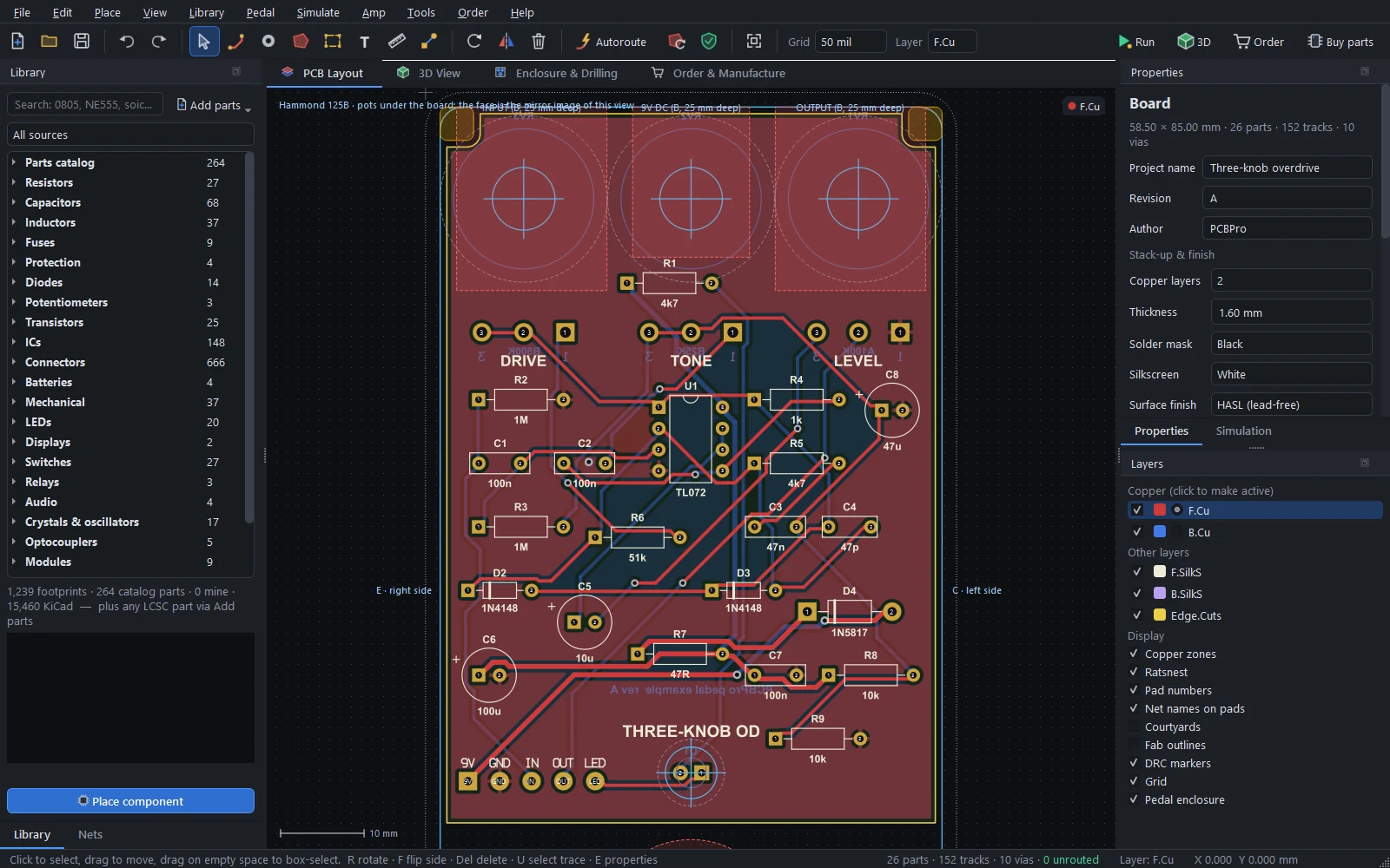
Start with Pedal › New pedal… (Ctrl+Shift+N), or open the three-knob overdrive from the start screen or Pedal › Open example: three-knob overdrive. The tutorial builds that example step by step; the metal pedals are in High-gain amps and pedals.
The new-pedal wizard#
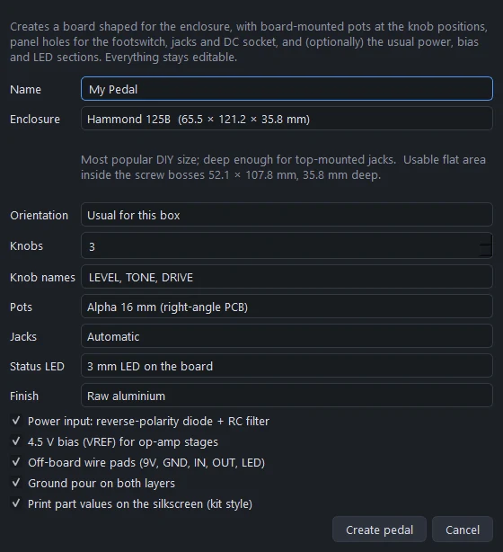
| Setting | Choices |
|---|---|
| Enclosure | Any Hammond box in the catalogue below, with its size and a line about what it suits |
| Orientation | Usual for this box, portrait or landscape |
| Knobs | 0 to 8, and their names (LEVEL, TONE, DRIVE, MID, BASS, TREBLE, BLEND, GATE...) |
| Pots | Alpha 16 mm (right-angle PCB) or Alpha 9 mm (vertical PCB). Tiny boxes (1590LB, 1590A) default to 9 mm. |
| Jacks | Automatic, top-mounted (pedalboard friendly), or side-mounted (input right, output left) |
| Status LED | 3 mm or 5 mm LED on the board, an LED in a panel bezel (wired), or none |
| Finish | Raw aluminium or a powder coat: black, white, cream, red, orange, yellow, green, teal, blue, purple, pink, gold or silver sparkle |
And five options, all on by default:
- Power input: a 1N5817 against reverse polarity, then 47R with 100u and 100n as an RC filter.
- 4.5 V bias (VREF) for op-amp stages: 10k / 10k and 47u.
- Off-board wire pads labelled 9V, GND, IN, OUT and LED.
- A ground pour on both layers.
- Part values printed on the silkscreen, kit style.
Create pedal makes:
- a board shaped for the enclosure's cavity, notched around the lid-screw bosses and clear of the footswitch and jacks;
- Alpha pots at the knob positions, laid out to fit the face, with their names on the silkscreen;
- panel holes for the footswitch, the jacks and the DC socket;
- the power, VREF and LED sections, with their nets;
- the wire pads, the ground pour, and through-hole-friendly design rules on a 1.27 mm grid.
Everything stays editable. Add the effect circuit from the Library and wire it with the Connect tool (see The layout editor).
Pedal › Insert circuit block drops the same blocks (power filter, VREF bias, status LED) into free space on any board later.
Enclosures#
| Box | Outside (mm) | Depth | Usable flat area inside the bosses | Suits |
|---|---|---|---|---|
| 1590LB | 50.6 × 50.6 | 27.0 | 37.0 × 37.0 | One knob and a footswitch |
| 1590A | 38.5 × 92.6 | 27.0 | 25.6 × 79.7 | Mini pedals: boosts, simple fuzzes, utilities |
| 1590B | 60.5 × 112.4 | 27.0 | 47.3 × 99.2 | The classic small pedal (2-3 knobs) |
| 1590BS | 60.5 × 112.0 | 38.0 | 46.6 × 98.1 | 1590B footprint with extra depth |
| 125B (1590N1) | 65.5 × 121.2 | 35.8 | 52.1 × 107.8 | The most popular DIY size; deep enough for top-mounted jacks |
| 1590BB | 94.0 × 119.5 | 30.0 | 78.9 × 104.4 | 4-6 knobs or two circuits |
| 1590BB2 | 94.0 × 119.5 | 33.8 | 80.1 × 105.6 | 1590BB with more depth |
| 1590XX | 121.2 × 145.2 | 35.2 | 105.3 × 129.3 | Complex builds and two footswitches |
| 1590DD | 120.0 × 188.0 | 33.0 | 103.9 × 171.9 | Multi-footswitch pedals (landscape) |
Each box has its drilled-face size, internal cavity, depth, wall thickness, wall draft, corner radius and the size and position of its lid-screw bosses. The cavity, depth and boss sizes come from Hammond's CAD data as tabulated by stompboxlayout.com. The face thickness is an estimate: measure your box before drilling.
In the layout editor the enclosure is drawn around the board: the cavity outline, the bosses, keep-outs where panel hardware hangs behind the face, and the wall names (mirrored correctly, see below). Toggle it with Pedal enclosure in the Layers panel. Pedal › Fit board outline to the enclosure reshapes the board to the cavity at any time; Centre on board (on the drilling tab) moves the enclosure to the board instead.
Mirroring, handled for you#
Most pedal boards hang from their pots: the pots are soldered to the back of the board, their shafts point through the face, and the board's components face the base plate. So the face of the enclosure sees the board from behind, and every drill coordinate is the mirror image of the layout.
PCBPro does that arithmetic. The enclosure's Board setting says which side faces the panel (Pots on the bottom side for the usual build), the layout says so in its top-left corner, and every hole on the drill template comes out where it belongs on the box. A pot placed on the wrong side is a DRC error.
The Enclosure & Drilling tab#
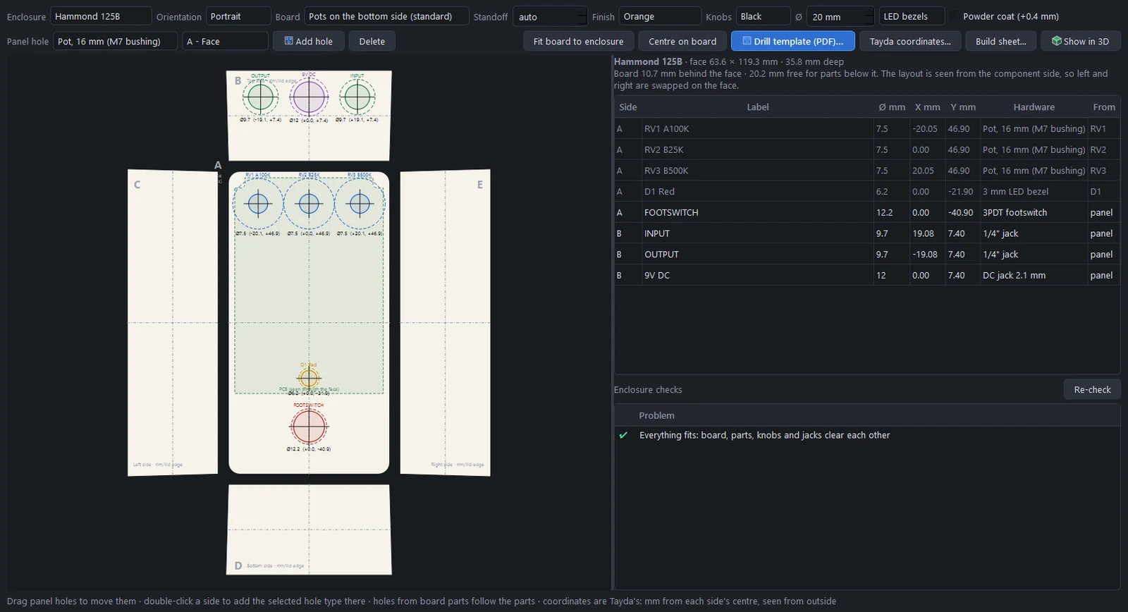
The box is drawn unfolded, in Tayda's convention: the face (A) in the middle, the top wall (B, with the jacks and DC socket of a top-jack pedal) above it, the left and right walls (C, E) beside it and the bottom wall (D) below. Coordinates are in mm from the centre of each side, +X right and +Y up, seen from outside.
At the top of the tab:
| Setting | What it does |
|---|---|
| Enclosure, Orientation | The box and which way up it stands |
| Board | Which side of the board faces the panel |
| Standoff | The gap between the board and the inside of the face (automatic from the pots, or your own) |
| Finish, Knobs, Ø | The powder coat, the knob colour and diameter (for the 3D view and the overlap checks) |
| LED bezels | Bezel holes instead of bare-LED holes for board LEDs |
| Powder coat (+0.4 mm) | Adds 0.4 mm to every hole for the paint |
The hole table lists every hole: side, label, diameter, X and Y, the hardware, and where it came from (a part on the board, or the panel). Holes come from two places:
- From the board. Pots, board-mounted switches, LEDs and PCB jacks carry their panel hole in their footprint, so their holes follow the parts as you move them.
- From the panel. Footswitches, chassis jacks, the DC socket, bezels, toggles, rotary switches and custom holes that aren't on the board. Pick a type in Panel hole and a side, then Add hole; or double-click a side in the drawing to add one there. Drag holes to move them, type coordinates in the table, or select one and Delete.
| Panel hole | Hole Ø (mm) |
|---|---|
| 16 mm pot (M7 bushing) | 7.5 |
| 9 mm pot | 7.2 |
| 3PDT footswitch | 12.2 |
| 1/4" jack | 9.7 |
| DC jack 2.1 mm | 12.0 |
| 3 mm / 5 mm LED | 3.2 / 5.2 |
| 3 mm / 5 mm LED bezel | 6.2 / 8.0 |
| Mini toggle / sub-mini toggle | 6.2 / 5.2 |
| Rotary switch | 10.0 |
| Custom | Your diameter |
The Enclosure checks list below the table re-runs as you edit (see Enclosure checks).
Drill outputs#
| Output | What it is |
|---|---|
| Drill template (PDF)… | A 1:1 printable template of the unfolded box with crosshairs at every hole, each hole's size, a coordinate table, and a 50 mm and a 1 inch scale bar to check the print. A4 or US Letter, from your system's measurement setting. |
| Tayda coordinates… | The holes as Tayda's drill designer takes them, as text or CSV. |
| Build sheet… | The parts list for the whole pedal (see Build sheet). |
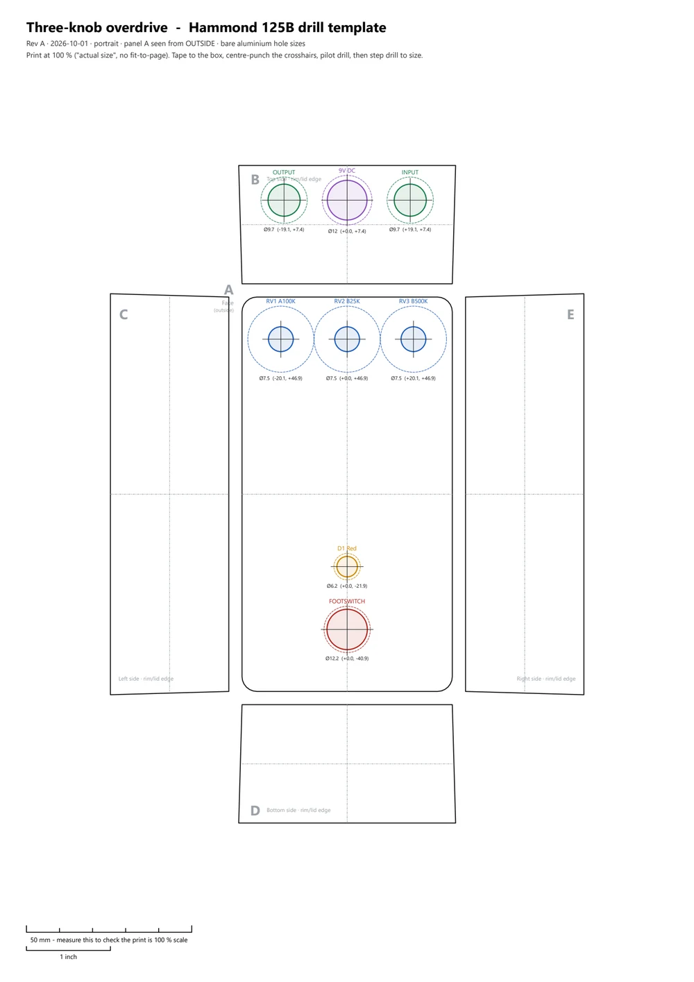
All three also go into the manufacturing package when you export the board. To have Tayda drill (and UV-print) the box for you, use Buy parts › Have Tayda drill the enclosure (see Buying components).
Before drilling, measure your actual parts and hold the printed template against the box and the board.
Enclosure checks#
When a design has an enclosure, the design rule check (F8, or Pedal › Run DRC with enclosure checks) adds:
- Fit. The board stays inside the usable area and clears the lid-screw bosses; the box is deep enough for where the board sits.
- Height. Every part fits between the board and the face (from each part's 3D model), and parts on the other side fit in the space down to the base plate. A tall electrolytic gets "lay it down, use a smaller part or a deeper enclosure".
- The right side. Pots, LEDs and board-mounted switches are on the side that faces the panel.
- Hardware. Hole overlaps, hardware bodies colliding behind the panel, and knobs or nuts overlapping each other or overhanging the face.
- Jacks and DC socket. Each wall hole is at a depth the wall can take, not too close to a corner, and its body doesn't hit the board, a part or another jack.
When everything is clear, the list on the drilling tab says Everything fits: board, parts, knobs and jacks clear each other.
Pedal parts#
| Part | Notes |
|---|---|
| Alpha 16 mm pot, PCB right-angle (RV16AF-41) | Pins 16 mm from the shaft, per the Alpha datasheet. Panel hole and body come with the footprint. |
| Alpha 16 mm dual-gang pot | For stereo or dual-ganged controls |
| Alpha 9 mm pot, PCB vertical | For small boxes |
| 3PDT footswitch, PCB pins | Board-mounted true bypass |
| DPDT and 3PDT mini toggles | On-on and on-off-on |
| Neutrik NMJ6HCD2 1/4" jack | Stereo, PCB mount; drills the wall it faces |
| DC jack 2.1 mm, centre-negative, PCB | |
| TO-92 transistors and JFETs | E-B-C, C-B-E, E-C-B, B-C-E, D-S-G, G-S-D and S-G-D, with lettered pads on a wide 2.54 mm grid for easy soldering |
| Wire pads | IN/OUT, 9V/GND, IN/GND/OUT, IN/OUT/9V/GND, the full 9V/GND/IN/OUT/LED strip, S/T, S/R/T, 1/2/3, A/K and LED+/LED- |
Panel parts carry their hole in the footprint (the face or wall it goes through, the hole diameter, its position and the body behind it), so they drill the enclosure on their own. The Alpha pot pattern and the Neutrik jack pattern and panel hole come from the datasheets. The 3PDT lug pitch, the jack axis heights and the typical hardware hole sizes are approximate: check them against your parts.
Kit-style silkscreen#
Pedal kits print each part's value next to it, so you can stuff the board without a parts list. Pedal › Silkscreen › Print part values on all parts does that for every part (and Remove part values takes them off); for one part, tick Show value in its Properties.
The build sheet#
Build sheet… (on the drilling tab, or Pedal › Export build sheet (BOM)…) writes a bill of materials grouped the way pedal builders shop: resistors; film, ceramic and electrolytic capacitors; semiconductors; pots; and hardware. The hardware lines come from the enclosure: the box itself, the knobs, dust covers for the pots, the footswitch, the jacks, the DC socket, bezels and hook-up wire. Save it as CSV or as text.
Buy components makes a shopping list from the same groups, with a search link at each shop.
The pedal in 3D#
Tick Pedal enclosure in the 3D view (or use Pedal › Show the pedal in 3D) to see the powder-coated box with its knobs, footswitch, LED bezel and jack nuts. Pedal view turns it knobs-up even when the pots hang under the board. See The 3D view.
Hear it before you build it#
Pedal boards can be simulated and played through: Simulate › Audio play-through renders a guitar clip through the circuit with the knobs as sliders, and Play live (Ctrl+Shift+L) runs your own guitar through it in real time.
Something wrong or missing on this page? Edit it on GitHub.